Improve the performances of A/D & D/A converters

Most of A/D & D/A converters used in studio recording are designed according to rather similar principles. What differentiates them is more the technology of their conversion chip and the neighboring electronic.
Nowadays, digital converters allow illimited possibilities of edition thanks to their interfaces and softwares. But what about the audio quality ? From the point of view of an electronic engineer, an A/D conversion is considered as a loss (even small) of quality.
Which sound engineer has never dreamed about being able to digitally record sound takes without the slightest loss of sound quality ? Which sound engineer has never dreamed about being able to "turn a mix" without any loss from the output of the mixing desk to the digital recording ? And if we tell you that this purely theoretical utopia can tend to become reality ? And if we tell you that it may be necessary to have a look to what almost nobody seems to consider ?
By following this article, we'll use two terms:
- Converter : the set constitued by the conversion chip and its digital electronics.
- Conversion device : the full device (generally called "converter") allowing the conversion of analog signals.
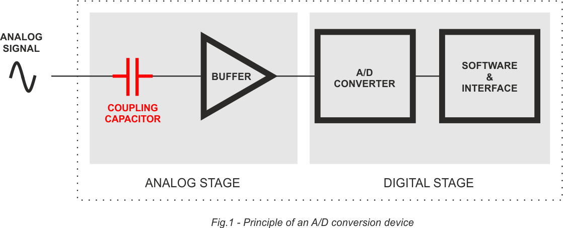
Figure 1 below illustrates the global principle of an A/D conversion device. This illustration aims to be very simplified to facilitate the understanding of the reader. First observation: an A/D conversion device is fitted with an analog stage and a digital stage.
This first stage is interesting us, particularly its coupling capacitor. This one allows to isolate electronic circuitries from any DC voltage. In other words, if an electric issue arises from a gear or a mixing desk at the input of the conversion device, there's no risk of damage or disturbance. Then one often finds a buffer stage. It's used to bring a constant and low impedance audio signal to the chip of conversion. A differential buffer is generally used when an input is of balanced type.

Why use the state-of-the-art A/D converter if its analog stage is fitted with a low cost coupling capacitor ?
Figure 1 above illustrates the importance of the coupling capacitor. Located at the beginning of the electronic circuit, it is a single component through which all the audio signal flows before conversion.
The main problem is that all the coupling capacitors degrade the audio signal which crosses them (dielectric properties). A lot of sound details disappear, stereophony width and sound depth are reduced. Digitally said,
the resolution of the audio signal decreases.
Audiophile people goes on war against coupling capacitors, considered as designing aberrations. However, it is often impossible to leave them. It's then very important to find the one which causes least losses, the one which degrades
least the audio signal which crosses it.
LEFSON designed three lines of coupling modules, the C-MOD (Coupling Module), to resolve this problem. The C-MOD does not color and does not almost degrade : it protects the characteristics of the audio signal which crosses it.
It thus becomes possible to considerably improve the audio quality of a majority of gears, while keeping their characteristics, their features, their original sound color.

From theory to practice !
To demonstrate our statements by the practice, we used a conversion device well known by the sound engineers. Who did not begin in that job with a DIGI 002? This one is fitted with 8 A/D inputs and 8
D/A outputs. We are going to focus on the A/D line inputs but the principle remains exactly the same regarding the D/A outputs, the coupling capacitor being then located at the end of the audio
chain, just before the output socket (XLR, Jack, RCA).
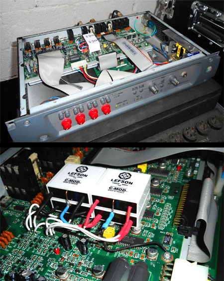
We replaced "ANALOG 7/8" coupling capacitors by LEFSON C-MOD HV of same capacity (100nF). Four C-MOD HV are necessary as each input is balanced. To notice the truthfulness of our words
we just have to record an audio source through the improved input "ANALOG 7/8" and through the original input "ANALOG 5/6".
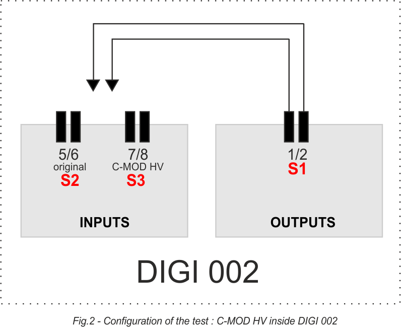
Figure 2 below illustrates the configuration of the test. The purpose is to determine through which input (C-MOD HV or original) the recording will be the least degraded, or in other words :
the most similar to the source. In a mixing session, the sound engineer would probably send the L/R bus of the console towards two inputs of the conversion device.
To perform our test, we use mixed audio clips and root them from the "ANALOG 1/2" outputs towards two "ANALOG 5/6" inputs for recording. We repeat the same operation through
"ANALOG 7/8" inputs. S1, S2 and S3 represent the audio signal in various places of the configuration. S1 is the reference signal, S2 and S3 each have been converted two times (one time D/A and an one A/D). However
the A/D conversion of S3 uses C-MOD HV. Three musical extracts are used and downloadable below. We strongly recommend you to listening to them on your professional monitors, or at worst with your headphones.
Between S2 et S3, Which signal is the most similar to S1 ?

- EXTRACT n°1 :
 S1 - Source signal
 S2 - Signal with original conversion
 S3 - Signal with C-MOD HV conversion
- EXTRACT n°2 :
 S1 - Source signal
 S2 - Signal with original conversion
 S3 - Signal with C-MOD HV conversion
- EXTRACT n°3 :
 S1 - Source signal
 S2 - Signal with original conversion
 S3 - Signal with C-MOD HV conversion
All extracts are .WAV, 44.1kHz / 24bits. To download them : right clic + "save link as".
Improve an A/D & D/A conversion device, while respecting scrupulously its original electronic design, thus becomes possible ! The LEFSON C-MOD HV used for the test above have only around 30 hours of operation. Better performances will occur from 80 hours, minimal burn-in time !

